 VLSI Solution Oy Evaluation MP3 Player Source Code Documentation
#include "AT89C51ED2-SFR.h"
Include dependency graph for board.h:
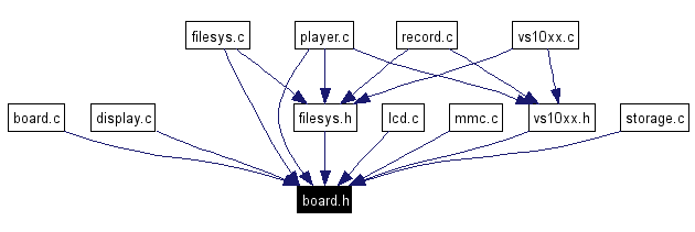
This graph shows which files directly or indirectly include this file:
Go to the source code of this file.
Classes | |
| union | Temp |
| Generic temp variable for non-reentrant main routines. More... | |
Defines | |
| #define | MP3_XRESET P2_4 |
| Chip Reset. | |
| #define | Mp3PutInReset() {MP3_XRESET=0;} |
| Put the MP3 player chip in reset. | |
| #define | Mp3ReleaseFromReset() {MP3_XRESET=1;} |
| Release the MP3 player chip from reset. | |
| #define | MP3_XCS P2_3 |
| Control Chip Select (for accessing SPI Control/Status registers). | |
| #define | Mp3SelectControl() {MP3_XCS=0;} |
| Pull the VS10xx Control Chip Select line Low. | |
| #define | Mp3DeselectControl() {MP3_XCS=1;} |
| Pull the VS10xx Control Chip Select line High. | |
| #define | MP3_XDCS P2_5 |
| Data Chip Select / BSYNC. | |
| #define | Mp3SelectData() {MP3_XDCS=0;} |
| Pull the VS10xx Data Chip Select line Low. | |
| #define | Mp3DeselectData() {MP3_XDCS=1;} |
| Pull the VS10xx Data Chip Select line High. | |
| #define | MP3_DREQ P3_2 |
| Data Request: Player asks for more data. | |
| #define | RED_LED P3_3 |
| Red LED in multicolor LED, 0 = on, 1 = off. | |
| #define | GREEN_LED P3_7 |
| Green LED in multicolor LED, 0 = on, 1 = off. | |
| #define | LED_ON 0 |
| LED is active low. | |
| #define | LED_OFF 1 |
| LED is inactive high. | |
| #define | KEY_BUTTON !(P1_2) |
| Center push-button, 1 when pressed. | |
| #define | KEY_FARRIGHT !(P1_1) |
| Far-left key, 1 when pressed. | |
| #define | KEY_RIGHT !(P1_0) |
| Left key, 1 when pressed. | |
| #define | KEY_LEFT !(P1_3) |
| Right key, 1 when pressed. | |
| #define | KEY_FARLEFT !(P3_4) |
| Far-right key, 1 when pressed. | |
| #define | LCD_DATABUS P0 |
| LCD Data pins are connected to DATA bus (P0). | |
| #define | LCD_RS P2_0 |
| LCD Register Select: 0=Control, 1=Data. | |
| #define | LCD_ENABLE P2_2 |
| LCD Clock Pulse (Active high). | |
| #define | LCD_RW 0 |
| LCD is only in write mode, read not possible. | |
| #define | LCD_COMMAND_MODE 0 |
| LCD RS is 0 in LCD Command Mode. | |
| #define | LCD_DATA_MODE 1 |
| LCD RS is 1 in LCD Data Mode. | |
| #define | RSEN P2_1 |
| RS-232 Buffer Enable. | |
| #define | YES 1 |
| YES = 1. | |
| #define | NO 0 |
| NO = 0. | |
| #define | MMC_OFF P2_7 |
| MMC Off (MMC Power Off). | |
| #define | MMC_XCS P2_6 |
| MMC Chip Select (Active Low). | |
| #define | MMC_SELECTED 0 |
| MMC is selected when MMC_XCS is low. | |
| #define | MMC_NOT_SELECTED 1 |
| MMC is not selected when MMC_XCS is high. | |
| #define | ClearPCAOverflow() {CCON &= 0x7f;} |
| Clear PCA core counter overflow flag. | |
| #define | PCARun() {CCON |= 0x40;} |
| Start Programmable Counter Array core counter. | |
| #define | PCAHalt() {CCON &= 0xBF;} |
| Stop Programmable Counter Array core counter. | |
| #define | PCAHaltAndClearOV() {CCON &= 0x3F;} |
| Stop PCA core counter and clear overflow flag. | |
| #define | SetPCAValue(v) {CH = ((unsigned)(v)) >> 8; CL = (v) & 0xff;} |
| Set PCA core counter value. | |
| #define | SetPCADelayValue(microseconds) {SetPCAValue(65535-(unsigned int)((microseconds)/0.4069010));} |
| Calculate and set Time-Until-Overflow to PCA in microseconds. | |
| #define | InitiateDelay(microseconds) {PCAHaltAndClearOV(); SetPCADelayValue(microseconds); PCARun();} |
| Initiate Delay of n microseconds. | |
| #define | WaitOutDelay() {while (!(CCON & 0x80));} |
| Busy loop until the end of the delay time. | |
| #define | SPISetFastClock() {SPCON=0x71;} /* 0x73 is much slower*/ |
| switch to fast SPI Clock | |
| #define | SPIWait() {while(!(SPSTA & 0x80));;} |
| Wait for SPI ready to send a new character (previous sent). | |
| #define | SPIPutChar(c) {SPIWait();SPDAT=(c);} |
| Wait for SPI ready, then initiate character sending. | |
| #define | SPIPutCharWithoutWaiting(c) {SPDAT=(c);} |
| Initiate SPI character sending. | |
| #define | SPI_RESULT_BYTE SPDAT |
| SPI data return register. | |
| #define | Public |
| "Public" has no code meaning but it is meant for the programmer to remember that this function is called from outside the module | |
Functions | |
| unsigned char | SPIGetChar () |
| Send 8 ones to SPI bus and receive the result byte. | |
| void | SPI8Clocks (unsigned char nClocks) |
| Send nClocks x 8 clock transitions with MOSI=1 (0xff). | |
| void | Delay (int milliseconds) |
| Busy loop delay function. | |
| void | InitBoard () |
| Startup initialization of the microcontroller board. | |
Variables | |
| Temp | temp |
| Generic temp variable for non-reentrant main routines. | |
--Define PCB2 for Evakit PCB V2.0+ Board related utility functions such as delay()
Required modules: -
Board Description:
VLSI Solution VS1011/VS1012/ Standard LCD Module: Tianma TM161A
Definition in file board.h.
|
|
Clear PCA core counter overflow flag.
|
|
|
Green LED in multicolor LED, 0 = on, 1 = off.
Definition at line 69 of file board.h. Referenced by GetAVIBlock(), PlayDiskSectors(), Record(), and VsSineTest(). |
|
|
Initiate Delay of n microseconds.
Definition at line 192 of file board.h. Referenced by Delay(), InitBoard(), LcdFadeIn(), LcdFadeOut(), LcdPutChar(), and LcdReset(). |
|
|
Center push-button, 1 when pressed.
Definition at line 83 of file board.h. Referenced by AvailableProcessorTime(), ConsoleDecipherMMCResponse(), main(), and Record(). |
|
|
Far-right key, 1 when pressed.
Definition at line 98 of file board.h. Referenced by AvailableProcessorTime(), and main(). |
|
|
Far-left key, 1 when pressed.
Definition at line 86 of file board.h. Referenced by AvailableProcessorTime(), and main(). |
|
|
Right key, 1 when pressed.
Definition at line 92 of file board.h. Referenced by main(). |
|
|
Left key, 1 when pressed.
Definition at line 89 of file board.h. Referenced by main(). |
|
|
LCD RS is 0 in LCD Command Mode.
Definition at line 123 of file board.h. Referenced by LcdPutCommand(). |
|
|
LCD RS is 1 in LCD Data Mode.
Definition at line 126 of file board.h. Referenced by LcdPutChar(). |
|
|
LCD Data pins are connected to DATA bus (P0).
Definition at line 111 of file board.h. Referenced by LcdPutChar(), and LcdPutCommand(). |
|
|
LCD Clock Pulse (Active high).
Definition at line 117 of file board.h. Referenced by LcdPutChar(), LcdPutCommand(), and LcdReset(). |
|
|
LCD Register Select: 0=Control, 1=Data.
Definition at line 114 of file board.h. Referenced by LcdPutChar(), and LcdPutCommand(). |
|
|
LCD is only in write mode, read not possible.
|
|
|
LED is inactive high.
Definition at line 75 of file board.h. Referenced by GetAVIBlock(), PlayDiskSectors(), ReadPhysicalSector(), Record(), VsSineTest(), and WritePhysicalSector(). |
|
|
LED is active low.
Definition at line 72 of file board.h. Referenced by GetAVIBlock(), PlayDiskSectors(), ReadPhysicalSector(), Record(), VsSineTest(), and WritePhysicalSector(). |
|
|
MMC is not selected when MMC_XCS is high.
Definition at line 159 of file board.h. Referenced by InitMMC(), MmcCommand(), MmcWaitForData(), ReadPhysicalSector(), SeekSector(), and WritePhysicalSector(). |
|
|
MMC Off (MMC Power Off).
Definition at line 150 of file board.h. Referenced by InitBoard(), InitMMC(), and MmcCommand(). |
|
|
MMC is selected when MMC_XCS is low.
Definition at line 156 of file board.h. Referenced by MmcCommand(), ReadPhysicalSector(), and WritePhysicalSector(). |
|
|
MMC Chip Select (Active Low).
Definition at line 153 of file board.h. Referenced by InitMMC(), MmcCommand(), MmcWaitForData(), ReadPhysicalSector(), SeekSector(), and WritePhysicalSector(). |
|
|
Data Request: Player asks for more data.
Definition at line 58 of file board.h. Referenced by GetAVIBlock(), Mp3Reset(), Mp3SoftReset(), PlayDiskSectors(), SendZerosToVS10xx(), and VsSineTest(). |
|
|
Control Chip Select (for accessing SPI Control/Status registers).
|
|
|
Data Chip Select / BSYNC.
Definition at line 43 of file board.h. Referenced by GetAVIBlock(). |
|
|
Chip Reset.
Definition at line 25 of file board.h. Referenced by InitBoard(). |
|
|
Pull the VS10xx Control Chip Select line High.
Definition at line 40 of file board.h. Referenced by Mp3ReadRegister(), Mp3Reset(), Record(), and VsSineTest(). |
|
|
Pull the VS10xx Data Chip Select line High.
Definition at line 49 of file board.h. Referenced by GetAVIBlock(), Mp3Reset(), Mp3SoftReset(), PlayDiskSectors(), SendZerosToVS10xx(), and VsSineTest(). |
|
|
Put the MP3 player chip in reset.
Definition at line 28 of file board.h. Referenced by Mp3Reset(), and VsSineTest(). |
|
|
Release the MP3 player chip from reset.
Definition at line 31 of file board.h. Referenced by Mp3Reset(), and VsSineTest(). |
|
|
Pull the VS10xx Control Chip Select line Low.
Definition at line 37 of file board.h. Referenced by Mp3ReadRegister(), and VsSineTest(). |
|
|
Pull the VS10xx Data Chip Select line Low.
Definition at line 46 of file board.h. Referenced by GetAVIBlock(), Mp3SoftReset(), PlayDiskSectors(), SendZerosToVS10xx(), and VsSineTest(). |
|
|
NO = 0.
Definition at line 147 of file board.h. Referenced by InitMMC(), and MmcCommand(). |
|
|
Stop Programmable Counter Array core counter.
|
|
|
Stop PCA core counter and clear overflow flag.
|
|
|
Start Programmable Counter Array core counter.
|
|
|
"Public" has no code meaning but it is meant for the programmer to remember that this function is called from outside the module
Definition at line 262 of file board.h. Referenced by BuildFragmentTable(), DumpDiskSector(), FGetChar(), InitFileSystem(), InitMMC(), InitStorage(), OpenFile(), PrepareToReadDiskSector(), ReadDiskSector(), ReadPhysicalSector(), SeekSector(), and WriteDiskSector(). |
|
|
Red LED in multicolor LED, 0 = on, 1 = off.
Definition at line 66 of file board.h. Referenced by ReadPhysicalSector(), VsSineTest(), and WritePhysicalSector(). |
|
|
RS-232 Buffer Enable.
|
|
|
Calculate and set Time-Until-Overflow to PCA in microseconds.
|
|
|
Set PCA core counter value.
|
|
|
SPI data return register.
Definition at line 223 of file board.h. Referenced by MmcCommand(), Mp3ReadRegister(), PerformBlockRead(), and SPIGetChar(). |
|
|
Wait for SPI ready, then initiate character sending.
Definition at line 217 of file board.h. Referenced by AvailableProcessorTime(), GetAVIBlock(), InitMMC(), MmcCommand(), Mp3ReadRegister(), Mp3SoftReset(), PlayDiskSectors(), SendZerosToVS10xx(), and VsSineTest(). |
|
|
Initiate SPI character sending.
Definition at line 220 of file board.h. Referenced by GetAVIBlock(), InitMMC(), MmcCommand(), Mp3ReadRegister(), Mp3Reset(), Mp3SoftReset(), PerformBlockRead(), PlayDiskSectors(), SendZerosToVS10xx(), SPI8Clocks(), SPIGetChar(), VsSineTest(), and WritePhysicalSector(). |
|
|
switch to fast SPI Clock
Definition at line 210 of file board.h. Referenced by Mp3Reset(). |
|
|
Wait for SPI ready to send a new character (previous sent).
Definition at line 214 of file board.h. Referenced by AvailableProcessorTime(), GetAVIBlock(), InitMMC(), MmcCommand(), Mp3ReadRegister(), Mp3SoftReset(), PerformBlockRead(), PlayDiskSectors(), SendZerosToVS10xx(), SPI8Clocks(), SPIGetChar(), VsSineTest(), and WritePhysicalSector(). |
|
|
Busy loop until the end of the delay time. In the delay system, the PCA core counter is used for hardware timing. First call InitiateDelay to put the counter running. Next do whatever work you can do while the delay is lasting. Lastly call WaitOutDelay to busy loop until the hardware says that the delay time has passed. This allows interrupt routines etc. to run during the delay without wasting unnecessary cycles at the delay loop.
Definition at line 203 of file board.h. Referenced by Delay(), LcdPutChar(), LcdPutCommand(), and LcdReset(). |
|
|
YES = 1.
Definition at line 144 of file board.h. Referenced by InitMMC(). |
|
|
Busy loop delay function. Creates n times 1 ms hardware delays Definition at line 35 of file board.c. References InitiateDelay, and WaitOutDelay. Referenced by InitMMC(), LcdPrintGenericResult(), LoadPatch(), Mp3Reset(), Mp3SoftReset(), RebootMMC(), Record(), and VsSineTest().
|
|
|
Startup initialization of the microcontroller board.
Definition at line 43 of file board.c. References InitiateDelay, MMC_OFF, and MP3_XRESET. Referenced by main().
|
|
|
Send nClocks x 8 clock transitions with MOSI=1 (0xff).
Definition at line 26 of file board.c. References SPIPutCharWithoutWaiting, and SPIWait. Referenced by MmcCommand(), MmcWaitForData(), ReadPhysicalSector(), and WritePhysicalSector().
|
|
|
Send 8 ones to SPI bus and receive the result byte.
Definition at line 18 of file board.c. References SPI_RESULT_BYTE, SPIPutCharWithoutWaiting, and SPIWait. Referenced by ConsoleDecipherMMCResponse(), MmcCommand(), MmcGetData(), MmcWaitForData(), and WritePhysicalSector().
|
|
|
Generic temp variable for non-reentrant main routines.
|